Build Guide
Visit the official repository to download the example code and get the latest version.
Bill of Materials
| # | Component | Notes |
|---|---|---|
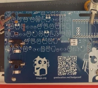
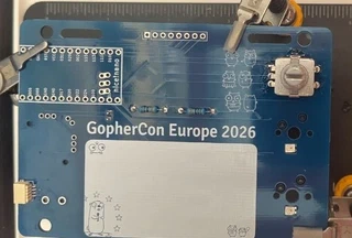
| 1 | PCB | NiceBadge PCB, see hardware/PCB-kicad/ |
| 1 | nice!nano | or compatible nRF52840 microcontroller board |
| 1 | ST7789 display | SPI 1.14" 135×240 px |
| 1 | Rotary encoder | Alps EC11E with push switch |
| 1 | Analog joystick | FJ08K-S |
| 1 | Passive buzzer | 5.5 mm |
| 2 | RGB LED | SK6812MINI-E (WS2812 compatible), bottom-mount |
| 2 | Pull-up resistor | 4.7 kΩ axial |
| 2 | Key switch | Cherry MX compatible |
| 2 | Key cap | MX stem |
| 2 | Key socket | Cherry MX hot-swap |
| 1 | Qwiic / StemmQT connector | JST SH 4-pin |
| 1 | Battery connector | JST 2.0 PH 2-pin |
| 2 | Flathead screw | M2.1 × 10 mm or M2.0 × 10 mm |
| 1 | Printed back cover | FDM printed, see hardware/stl/ |
| 1 | Printed front frame | FDM printed, see hardware/stl/ |
Tools
- Soldering iron + solder
- Flux
- Fine-tip tweezers
- Helping hands or PCB holder
- Isopropyl alcohol + brush (cleanup)
Assembly Steps
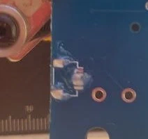
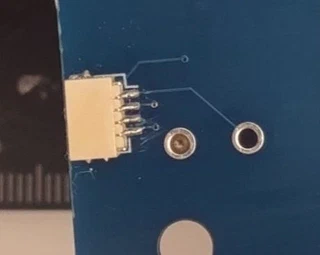
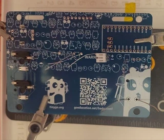
Step 1 - Solder the StemmQT connector (back)
Solder the JST SH 4-pin Qwiic / StemmQT connector on the back of the PCB. The connector is surface-mounted; you might use some flux to help you with the process, add some solder to the board, put the connector and push gently with the iron.
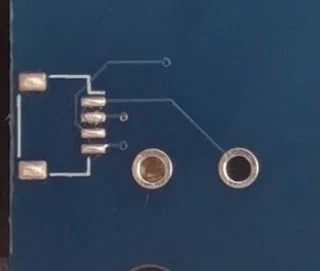
Step 2 - Solder back-side SMD components
Solder the two SK6812MINI-E RGB LEDs on the back of the PCB. The SK6812MINI-E is a bottom-mount LED - the light emits downward through the board cutouts. Check the orientation mark on each LED package before soldering.
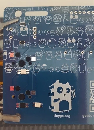
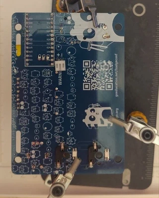
Step 3 - Solder the key sockets and the battery connector
Solder the two Cherry MX hot-swap sockets on the back of the PCB. Press each socket firmly into the pad before and during soldering so it sits flat.
Solder the JST 2.0 PH 2-pin battery connector on the back.
Double-check polarity - the + pad is marked on the silkscreen.
Step 4 - Solder the rotary encoder and the resistors
Flip the board. Insert the Alps EC11E rotary encoder and the two 4.7 kΩ pull-up resistors through the front and solder on the back. Make sure the encoder sits flush against the PCB before soldering all pins.
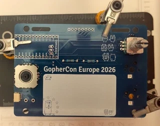
Step 5 - Solder the analog joystick
Insert the Alps EC11E analog joystick module in the left footprint and solder all 5 pins.
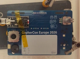
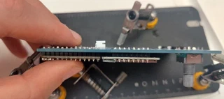
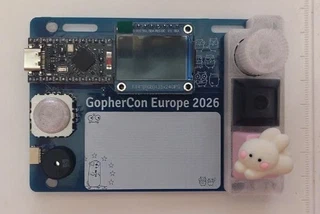
Step 6 - nice!nano, buzzer & display
Insert the two pin header strips (or Mill-Max sockets) for the nice!nano. Keep them perfectly vertical - use the nice!nano itself as a alignment guide without soldering it yet.
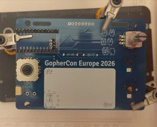
Press the nice!nano onto the pin headers. The USB-C port should face the left edge of the badge. Solder the nice!nano to the headers.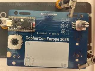
Optionally place a strip of kapton tape over the nice!nano to hold it in place while soldering on the back side. Put the buzzer and display too.
Solder everything on the back side.
Step 8 Trim excess
Everything is solder now, use some plipers to cut excess of the headers on both sides.
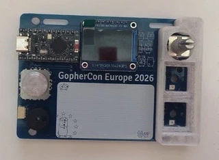
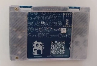
Step 9 - Place plastic parts
Place the plastic parts: front and back covers, also rotary know and joystick hat.
Place the printed back cover over the rear of the PCB, aligning the mounting holes. Secure it with the two M2.1 × 10 mm flathead screws.
Step 10 - Install the key switches
Press the two Cherry MX key switches into the hot-swap sockets from the front. The pins must click fully into the socket - a half-seated switch will not make contact.
⚠️ BE CAREFUL to not bend the contacts while inserting them.
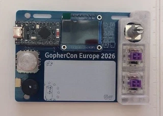
Press the keycaps onto the key switch stems until they click into place.
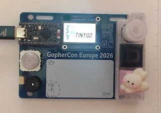
Step 11 - Flash the firmware and test
Connect the badge to your computer via USB-C and flash the demo firmware:
cd tutorial
tinygo flash -target nicenano ./basics/step0
Verify the display turns on and all peripherals respond before closing the battery compartment.
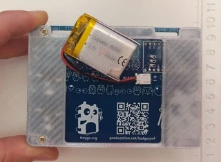
Step 12 - Optional: connect a battery
Connect the LiPo battery to the JST 2.0 connector on the back. You can use a velcro patch to secure the battery to the back
⚠️ Observe polarity - red wire to
+, black wire to−. Reversing polarity will damage the nice!nano.
Done
Your NiceBadge is ready. Here’s where to go next:
- Tutorials - step-by-step TinyGo programming guide
- Examples - standalone, feature-complete programs
- Configurator - customize your badge online