Information
Visit the official repository to download the example code and get the latest version.
A custom WS2812 LED badge powered by a Seeed XIAO (BLE/RP2040/ESP32C3/…) and written in TinyGo.
The PCB hosts 20 RGB LEDs arranged in a 4 rows × 5 columns grid behind a frosted 3D-printed diffuser. A single button cycles through lighting effects.
Hardware
| Component | Note |
|---|---|
| Hikari PCB | in hardware/pcb folder |
| 3D printed files | in hardware/STL folder |
| Flathead screw 2.1x10 | 4x |
| 20 × WS2812 LEDs (4 rows × 5 cols) | D6 |
| Tactile button | D3 |
| Qwiic / StemmaQT connector | D4 & D5 (I²C) |
| Passive buffer | D7 |
Effects
Each press of the button advances to the next effect. The sequence cycles endlessly.
| # | Name | Description |
|---|---|---|
| 1 | Rainbow | All 20 LEDs show the same colour; the hue cycles slowly through the full spectrum (~20 s per revolution) |
| 2 | Row sweep | One row lights up at a time and sweeps downward; the hue drifts continuously |
| 3 | Column sweep | One column lights up at a time and sweeps rightward |
| 4 | Stars | 8 LEDs at random positions fade in with a random colour then fade out; when a star dies a new one appears elsewhere |
| 5 | Breathing | All LEDs pulse with a triangular brightness envelope (~5 s per breath); the hue shifts slowly between cycles |
| 6 | Rainbow rows | Each row shows a different hue (90° apart on the colour wheel); all hues advance together |
| 7 | Wave | A bright column chases across the grid with a two-column fading trail |
Flash
tinygo flash -target=xiao-esp32c3 -stack-size=8KB .
Requires TinyGo ≥ 0.41 and tinygo.org/x/drivers v0.35.
Build
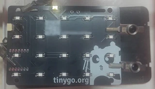
Step 1 - Bare PCB
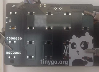
The back side of the custom PCB. Footprints for the 20 WS2812 LEDs are arranged in the 4 × 5 grid.
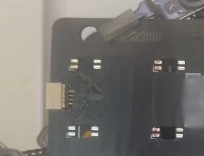
Step 2 - Qwiic / StemmaQT connector
We’ll start with the SMD Qwiic / StemmaQT connector since it’s the trickiest to solder. It is not really needed, but a cool way to extend the board with sensors. Use the help of some flux if needed.
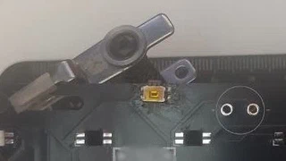
Step 3 - Soldering the button
The tactile switch is soldered to its footprint on top of the board. Easier than the stemmaQT.
Step 4 - PCB fully populated
All 20 LEDs and the button in place. The XIAO BLE/RP2040/ESP32C3/… plugs in on the left edge. It’s the easier one to do, and the last one to be done since it goes over one LED.
NOTE: Make sure all the LEDs are correctly soldered since once we solder the board there’s no way to fix the LED behind it.
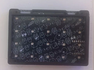
Step 5 - PCB seated in the frame
The board drops into the back shell. The silkscreen on the rear shows the Go gopher pattern.
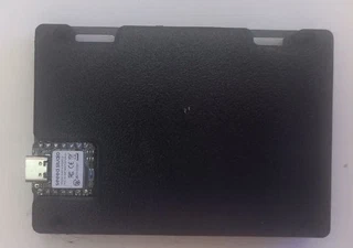
Step 6 - 3D-printed back cover
The black back shell printed in PLA. The XIAO slides into the slot on the side for USB access. Use 4 screws on the holes.
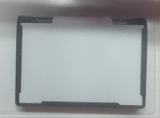
Step 7 - Frosted diffuser panel
A white PLA diffuser snaps onto the front of the frame to spread the light evenly across the grid. You could print different models of the diffuser!
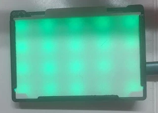
Step 8 - Finished
Fully assembled and running. The diffuser softens each LED point into a smooth glow.
Showroom